October 16, 2026
One More Resistance in Series
The overall heat transfer coefficient of an exchanger is built from resistances in series: the film on the inside of the tube, the tube wall, and the film on the outside, 1/U = 1/h_i + R_wall + 1/h_o, with each term referred to a common area. On day one, that is the whole story. After weeks or months in service, though, scale, sludge, biological growth, or corrosion products build up on one or both surfaces, and each deposit adds its own thermal resistance to the chain.
Those fouling resistances, R_f,i and R_f,o, simply add to the sum. Because they are in series with everything else, a deposit only a fraction of a millimetre thick can matter more than the metal wall, since most deposits conduct heat poorly. The exchanger's U falls steadily over time, the outlet temperatures drift, and eventually the unit has to be cleaned.
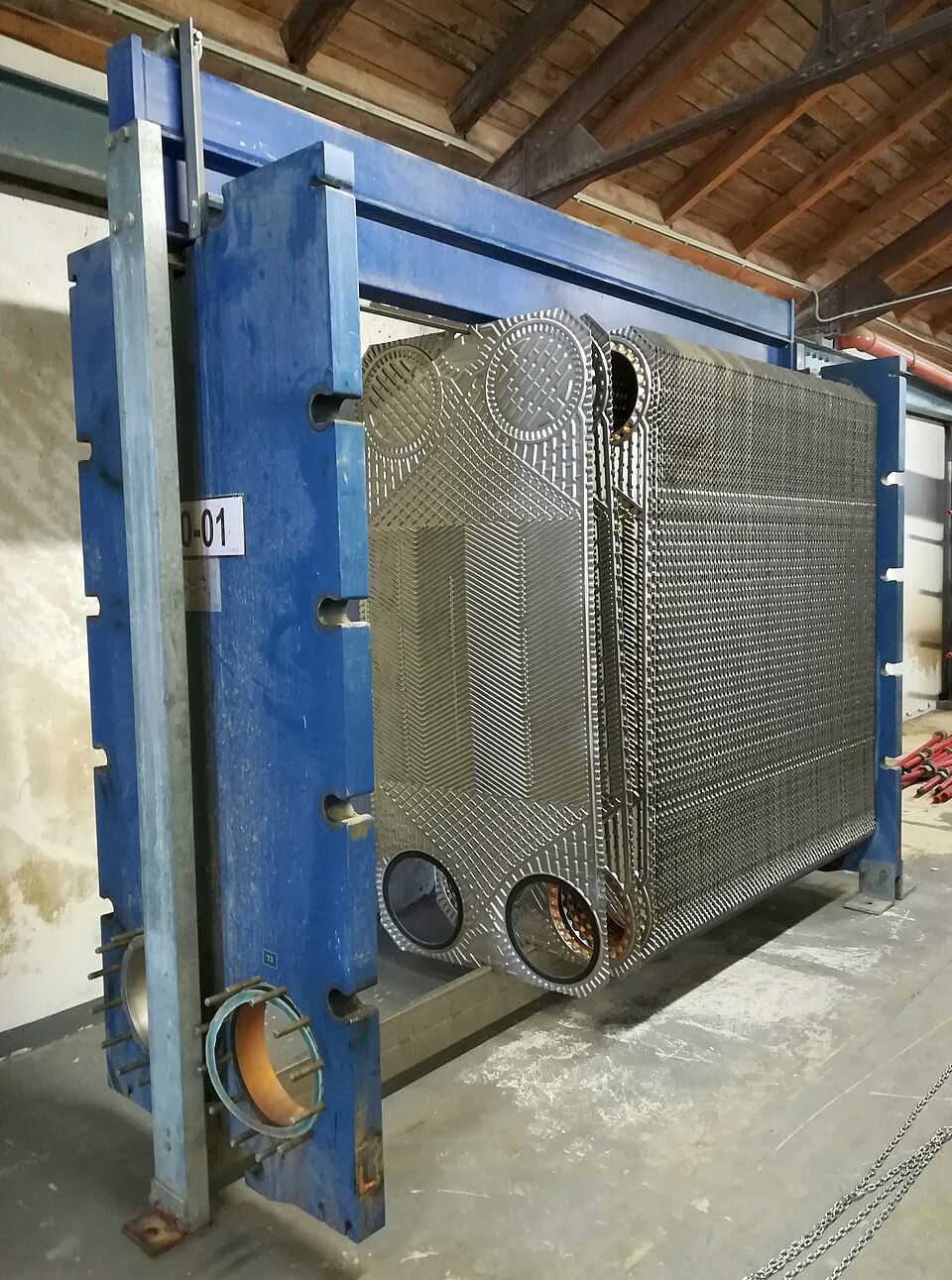
What Fouling Actually Is
Norman Epstein's 1983 paper organised the subject into a five-by-five matrix that is still widely used. Along one axis are five mechanisms: crystallisation of dissolved salts, such as calcium carbonate scale in cooling water; deposition of suspended particles; chemical reaction fouling, such as coke forming from hot hydrocarbons; corrosion; and biological fouling from microbes, algae, or mussels. Along the other are five sequential stages: initiation, transport to the surface, attachment, removal, and ageing of the deposit.
That framing makes clear that fouling is a balance between deposition and removal. Kern and Seaton's 1959 model expressed this as a fouling resistance that approaches an asymptote over time, R_f = R_f*·(1 − e^(−t/θ)): deposits build up until the shear from the flowing fluid strips material away as fast as it arrives. Some services foul toward such a plateau, while others, like crude oil preheat trains, keep fouling steadily.
Fouling Factors as a Design Margin
Because fouling is hard to predict from first principles, designers usually include fixed fouling resistances taken from tables, most famously those published by TEMA. A typical value for treated cooling tower water is in the range of 0.0002 to 0.0004 m²·K/W. The exchanger is then sized with this fouled U, so that it still meets duty when dirty.
The penalty depends heavily on how good the clean coefficient is. Suppose clean U is 2000 W/m²·K, a resistance of 0.0005 m²·K/W. Adding total fouling resistance of 0.0004 m²·K/W brings the sum to 0.0009, so U drops to about 1100 W/m²·K and the exchanger needs about 80% more area. For a gas-gas exchanger with a clean U of 50 W/m²·K, the same fouling resistance changes the area by only a couple of percent. Fouling factors hurt most exactly where heat transfer is otherwise excellent.
Why Oversizing Can Make Fouling Worse
Generous fouling factors seem safe, but they can backfire. A heavily oversized exchanger is often given extra tubes, which spreads the same flow over more of them and lowers the velocity in each. Lower velocity means lower wall shear, less deposit removal, and in many services faster fouling. The exchanger then fouls until it reaches the performance the oversizing was meant to protect against.
For that reason, modern practice treats fouling as something to design against rather than simply add area for. Keeping tube-side velocities high, commonly above about 1 to 2 m/s for cooling water, putting the fouling fluid on the tube side where it is easier to clean, controlling water chemistry, and planning for periodic cleaning all reduce the need for large blanket fouling factors.
References
- Kern, D. Q. (1950). Process Heat Transfer. New York: McGraw-Hill.
- Kern, D. Q., & Seaton, R. E. (1959). A theoretical analysis of thermal surface fouling. British Chemical Engineering, 4(5), 258–262.
- Epstein, N. (1983). Thinking about heat transfer fouling: A 5 × 5 matrix. Heat Transfer Engineering, 4(1), 43–56. doi:10.1080/01457638108939594
- Tubular Exchanger Manufacturers Association. (2019). Standards of the Tubular Exchanger Manufacturers Association (10th ed.). Tarrytown, NY: TEMA.
- Shah, R. K., & Sekulić, D. P. (2003). Fundamentals of Heat Exchanger Design, Chapter 13. Hoboken, NJ: Wiley. doi:10.1002/9780470172605